Xylem 19 001 251 R3 Floboy VFD Pumping System User Manual
Browse online or download User Manual for Pumps Xylem 19 001 251 R3 Floboy VFD Pumping System. Xylem 19 001 251 R3 Floboy VFD Pumping System User Manual
- Page / 40
- Table of contents
- TROUBLESHOOTING
- BOOKMARKS
- VFD Pumping System 1
- Acknowledgements 2
- TABLE OF CONTENTS 3
- TABLE OF FIGURES 4
- WARRANTY INFORMATION 6
- SAFETY INSTRUCTION 7
- SAFETY APPAREL: 8
- COUPLING GUARDS: 8
- OPERATION: 8
- MAINTENANCE SAFETY: 8
- GENERAL DESCRIPTION 9
- RECEIVING 12
- INSTALLATION 12
- Properly 13
- CAUTION 16
- START-UP AND ADJUSTMENTS 17
- WARNING 18
- STATION OPERATION 20
- NAVIGATING THE CONTROLS 25
- : Equipment Damage Hazard 26
- MAINTENANCE 30
- TROUBLESHOOTING 32
- GLOSSARY OF TERMS 36
- Warning: Rotating Shafts 39
- Xylem Inc 40
Summary of Contents
Floboy™VFD Pumping SystemINSTRUCTION MANUAL19-001-251R3NOTE: This product is not intended for use in potable water applications.INSTALLER: PLEASE LEAV
6 Figure 3: Sample Nameplate Field Explanation Voltage Required input voltage SCCR Short circuit current rating Phase Number of motor phases FLA Ful
7 HANDLING Qualified personnel should unload and handle the unit. Prevent damage due to dropping or jolting when moving the unit. Thoroughly inspect t
8 RECEIVING PREPARING TO RECEIVE THE PUMP STATION Each Floboy Pumping System is shipped on a wooden pallet and is enclosed in either a cardboard box o
9 Concrete slabs should be at least 6" thick and be constructed in a monolithic pour from 3000 psi concrete and #5 rebar. The slab should be size
10 A. Piping should be sized in accordance with the architect, engineer or factory's direction. B. Piping should be constructed of spring reinf
11 Figure 6: Proper suction lift principles Figure 7: Improper suction lift application
12 DISCHARGE PIPING Like the suction assembly, the discharge piping requires adherence to certain rules and conditions in order to minimize future pro
13 START-UP AND ADJUSTMENTS Floboy Pumping Systems are pre-tested in the factory and all controls are adjusted for the operating conditions specified.
14 water when the motor is energized. For pump stations whose inlet is supplied with water under pressure or from an elevated reservoir, the priming p
15 Figure 9: Confirm rotation by making sure motor is operating in the direction of the motor tag SYSTEM PRESSURIZATION With the system isolation val
Acknowledgements All materials ©2013 by Flowtronex®, an Xylem company. Flowtronex® is a registered trademark of Xylem Flowtronex. All rights reserv
16 STATION OPERATION This section covers the sequence of operation for your station including: Door Switch Operation, Automatic Operation, and System
17 AUTOMATIC OPERATION Overview The primary benefit of Variable Speed Pumping (VSP) Systems is to ensure surge-free starts and stops while maintaining
18 pressure at the set point. This is the operation sequence for Combo 2. When the flow decreases, the VFD slows down to maintain a constant discharge
19 CONTROLLER BYPASS OPERATION Overview This is an abnormal operating mode and would be used if the controller was not operable and there is need to
20 reference to set point). There is a time delay of 60 seconds, before the station faults that is designed to give the system time to adjust the pres
21 INDIVIDUAL PUMP FAULTS Pump faults are usually caused by the thermal overload tripping, or circuit fault that causes the pump NOT to start when req
22 Figure 10: Floboy controller. The “Menu” key provides access to the slide-out menu which can be touched directly for navigation and also serves
23 Figure 15: Entering the password for the set point screen This allows the user to edit the set point. Touch the button next to the Set point va
24 Pressing the Menu button from the main screen provides access to the menu system. Figure 20: Menu Access to the main functions of the controller
25 Figure 25: Speed Test SPEED TEST: Delay is how long the controller waits before initiating speed test (after all other shutdown parameters are sa
TABLE OF CONTENTSACKNOWLEDGEMENTS II TABLE OF CONTENTS ·········································· I TABLE OF FIGURES ·······························
26 MAINTENANCE Maintenance is an investment that will pay dividends in the form of improved reliability and durability. Site maintenance checks are a
27 WINTERIZING THE PUMP STATION CAUTION: Equipment Damage Hazard Your pumping system must be properly winterized before storage. Failure to
28 TROUBLESHOOTING 1. If a troubleshooting step needs to be performed by a qualified person, it is labeled “To be performed by a qualified person onl
29 Bad relief valve or pilot valve seat. Rebuild or replace valve. Low suction pressure or supply water restriction. Call the city if the city water p
30 Inlet pressure switch is set too high. To be performed by a qualified person only. Check the pressure switch setting. (Located on lower left side
31 Fault code 2 – DC overvolt (intermediate circuit DC voltage is excessive). To be performed by a qualified person only. Check the input voltage (AC
32 GLOSSARY OF TERMS AC Alternating Current. The voltage, and therefore current, constantly oscillates positive and negative. For North America, the
33 Foot valve A device used primarily on horizontal lift applications to maintain pump prime. Frequency (Hz) The number of oscillations per second of
34 Speed test The method used to shut down a VSP during normal automatic operation. Temperature switch This is a normally open or normally closed swit
35 APPENDIX A — FINAL CHECK LIST ! Is the base unit properly leveled and secured? ! Are all lubrication points properly lubricated? ! Is the shut-off
TABLE OF FIGURESFigure 1: Typical Floboy suction and discharge piping, Boost applications ... 5
Xylem Inc. 10661 Newkirk StreetDallas, TX 75220Phone: [email protected] is a trademark of Xylem Inc. or o
NOTE: The information contained in this book is intended to assist operating personnel by providing information about the characteristics of the purc
2 WARRANTY INFORMATION Company warrants title to the product(s) and, except as noted below with respect to items not of Company’s Manufacturer, also
3 SAFETYRead all safety information prior to installation of your pumping system. SAFETY INSTRUCTIONS SAFETY INSTRUCTION This is a SAFETY ALERT SYMBO
4 ADDITIONAL SAFETY INFORMATION This pump has been designed for safe and reliable operation. A pump is a pressure-containing device with rotating pa
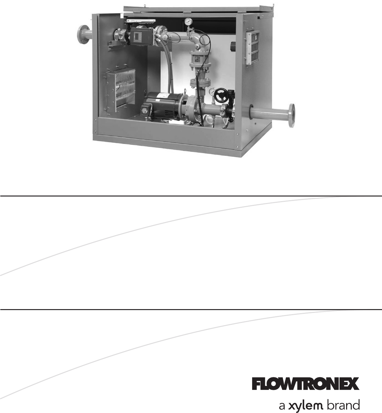
GENERAL DESCRIPTION PRODUCT DESCRIPTION Floboy Pumping Systems are self-contained, pre-assembled and factory-tested pumping systems. Floboy utilizes
Related products and manuals for Pumps Xylem 19 001 251 R3 Floboy VFD Pumping System
 (52 pages)

 (40 pages)
© 2020, manymanuals.com. All rights reserved. | 0.046 s |
 Manymanuals.com
 Manymanuals.de
 Manymanuals.fr
 Manymanuals.it
 Manymanuals.pl
 Manymanuals.cz
 Manymanuals.es
 Manymanuals-pt.com
Comments to this Manuals